×
- Hello
- Login or Register
- Quick Links
- Live Chat
- Track Order
- Parts Availability
- RMA
- Help Center
- Contact Us
- Shop for
- Hyundai Parts
- Hyundai Accessories


My Garage
My Account
Cart
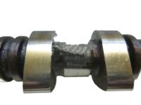
Genuine Hyundai Santa Fe Camshaft
Cam- Select Vehicle by Model
- Select Vehicle by VIN
Select Vehicle by Model
orMake
Model
Year
Select Vehicle by VIN
For the most accurate results, select vehicle by your VIN (Vehicle Identification Number).
51 Camshafts found

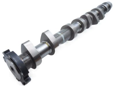
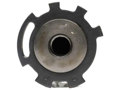
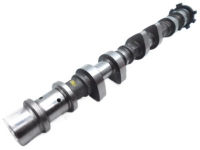
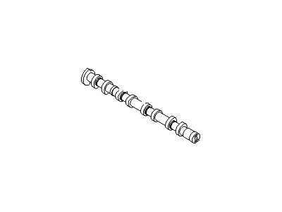
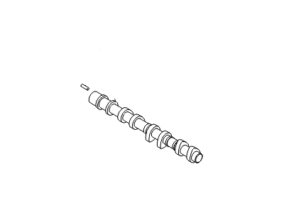
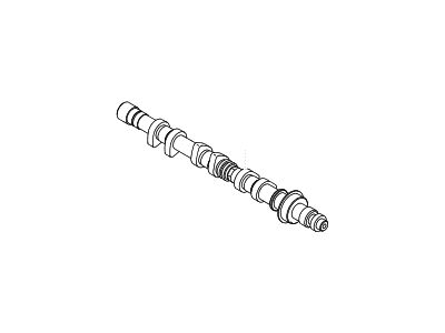
Hyundai Santa Fe Camshaft Assembly-Intake,LH
Part Number: 24100-3CGA0$233.11 MSRP: $327.52You Save: $94.41 (29%)Ships in 1-3 Business Days
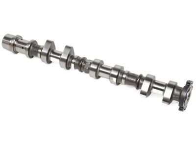
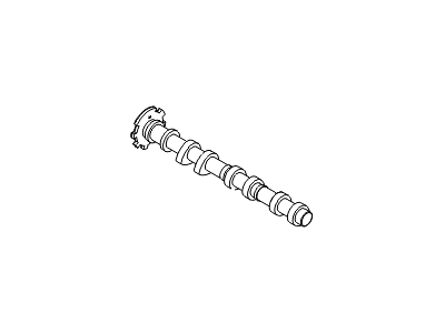
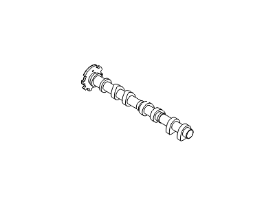
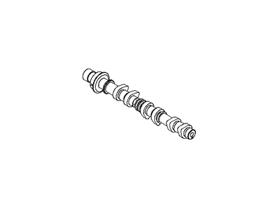
Hyundai Santa Fe CAMSHAFT Assembly-Intake,RH
Part Number: 24900-3CBE2$364.13 MSRP: $516.08You Save: $151.95 (30%)Ships in 1-3 Business Days
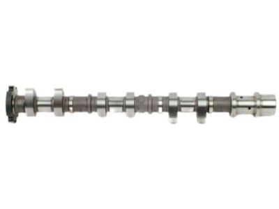
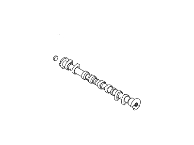
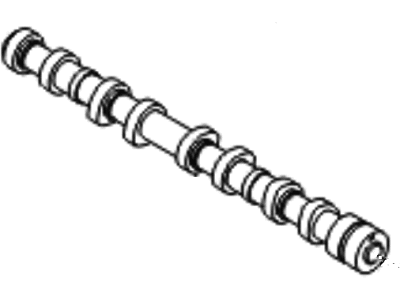
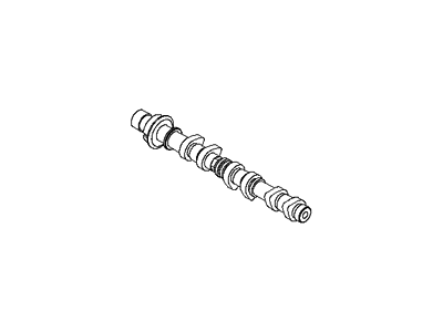
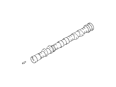
Hyundai Santa Fe Camshaft Assembly-Intake,LH
Part Number: 24100-3CBE2$377.33 MSRP: $534.79You Save: $157.46 (30%)Ships in 1-3 Business Days
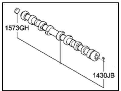
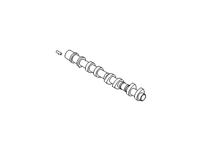
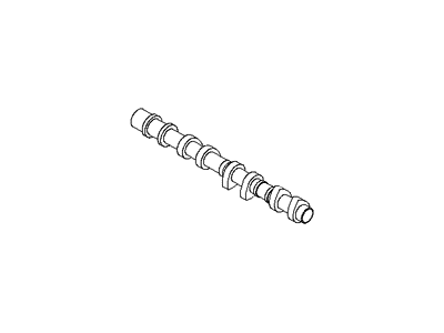
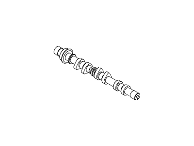
Hyundai Santa Fe CAMSHAFT Assembly-Intake,RH
Part Number: 24900-3CAB1$214.66 MSRP: $301.60You Save: $86.94 (29%)Ships in 1-3 Business DaysHyundai Santa Fe Camshaft Assembly-Intake
Part Number: 24100-2GTB0$201.70 MSRP: $283.39You Save: $81.69 (29%)Ships in 1-3 Business DaysHyundai Santa Fe Camshaft Assembly-Exhaust
Part Number: 24200-2GTA0$201.70 MSRP: $283.39You Save: $81.69 (29%)Ships in 1-3 Business DaysHyundai Santa Fe Camshaft Assembly-Intake
Part Number: 24100-2G600$201.70 MSRP: $283.39You Save: $81.69 (29%)Ships in 1-3 Business DaysHyundai Santa Fe Camshaft Assembly-Exhaust
Part Number: 24200-2GGA0$250.82 MSRP: $352.39You Save: $101.57 (29%)Ships in 1-3 Business DaysHyundai Santa Fe Camshaft Assembly-Intake,LH
Part Number: 24100-3C705$377.33 MSRP: $534.79You Save: $157.46 (30%)Ships in 1-3 Business DaysHyundai Santa Fe Camshaft Assembly-Exhaust
Part Number: 24200-2G600$188.49 MSRP: $264.82You Save: $76.33 (29%)Ships in 1-3 Business DaysHyundai Santa Fe Camshaft Assembly-Exhaust,LH
Part Number: 24200-3CBD0$263.97 MSRP: $370.87You Save: $106.90 (29%)Ships in 1-3 Business DaysHyundai Santa Fe Camshaft Assembly-Exhaust,RH
Part Number: 24700-3CBD0$263.97 MSRP: $370.87You Save: $106.90 (29%)Ships in 1-3 Business DaysHyundai Santa Fe Camshaft-Intake,RH
Part Number: 24910-3E010$269.93 MSRP: $379.24You Save: $109.31 (29%)Ships in 1-3 Business DaysHyundai Santa Fe Camshaft-Intake,RH
Part Number: 24910-3E050$269.93 MSRP: $379.24You Save: $109.31 (29%)Ships in 1-3 Business DaysHyundai Santa Fe Camshaft Assembly-Exhaust,RH
Part Number: 24700-3C505$290.52 MSRP: $408.18You Save: $117.66 (29%)Ships in 1-3 Business DaysHyundai Santa Fe Camshaft-Intake,RH
Part Number: 24910-37201$293.46 MSRP: $412.31You Save: $118.85 (29%)Ships in 1-3 Business DaysHyundai Santa Fe Camshaft-Intake,RH
Part Number: 24910-37211$293.46 MSRP: $412.31You Save: $118.85 (29%)Ships in 1-3 Business DaysHyundai Santa Fe Camshaft Assembly-Exhaust,LH
Part Number: 24200-3CBE1$277.16 MSRP: $389.40You Save: $112.24 (29%)Ships in 1-3 Business DaysHyundai Santa Fe CAMSHAFT Assembly-Intake,RH
Part Number: 24900-35700$661.19 MSRP: $937.11You Save: $275.92 (30%)Ships in 1-3 Business Days
| Page 1 of 3 |Next >
1-20 of 51 Results
Hyundai Santa Fe Camshaft
If you are looking for affordable high-quality OEM Hyundai Santa Fe Camshaft, then you have come to the prime place. Our website provides a large amount of genuine Hyundai Santa Fe Camshaft at unbeatable prices. All our parts come backed with the manufacturer's warranty.
Hyundai Santa Fe Camshaft Parts Questions & Experts Answers
- Q: How to remove and install Camshaft on V6 Hyundai Santa Fe?A:If it is necessary to unbolt the Variable Valve Timing (VVT) assembly on the intake camshaft sprockets do not dismantle it-instead, to release it, unbolt the center nut on the extremity of the camshaft. Firstly, bring the engine to the top dead center and then unbolt the engine valve covers and the timing belts or chains. Make sure that marks line up between the sprockets and block on the engine; Camshafts cannot be swapped and should be marked to indicate position. For the first operation, turn the camshaft bearing cap bolts by 1/4 turn and afterward, place the bearing caps in a cardboard box since they may be interchanged; you can even number the bearing caps if possible. Very carefully, extract the camshaft, and it is necessary to mark that in some motors, the cams are taken out jointly since they are connected by a timing chain. Lay the bearing caps side by side and in their correct positions and if necessary, take out the valve hydraulic adjusters and the rocker arms or the lifters and place them in a manner that will enable them to be fitted again. To the camshaft lobes and bearing journals, use the camshaft installation lubricant; put the lower lash adjusters and the lower rocker arms or lifters back into their prior locations. Mount the timing chains around the sprockets moving them into position on the timing marks. Replace each of the cams to its original position ensuring that the timing marks align with the colored links on the chains. Screw in the bearing caps in numerical sequence one after the other starting from the center cap while using only a 1/4 turn on each bolt. If necessary replace the camshaft oil seal with a new one and than put back the other components in the reverse order making sure the timing marks match or the major damages are to be expected. Before starting an engine that has not been used for an extended period make make sure there are no drips or that everything is in order and that it might take sometimes for the valvetrain noise to dissipate if hydraulic valve adjusters were flushed. For valve clearence adjustments remove the valve cover and set number one cylinder to TDC on the compression stroke Departments. Check the clearance with the feeler gauge and write down the measurements of the camshaft lobes and the lifters. Turn the engine a little clockwise and repeat the measurement on the other valves of the engine. Should any of the clearances be beyond specifications remove the camshaft and lifter that is in the wrong position, and measure it using a micrometer. To select the right thickness if any replacement lifter you must apply the above formula, get the correct thickness lifter to be installed, and after the job, it is also important to measure clearances to the recommended range.
Related Hyundai Santa Fe Parts
Browse by Year
2023 Camshaft 2022 Camshaft 2021 Camshaft 2020 Camshaft 2019 Camshaft 2018 Camshaft 2017 Camshaft 2016 Camshaft 2015 Camshaft 2014 Camshaft 2013 Camshaft 2012 Camshaft 2011 Camshaft 2010 Camshaft 2009 Camshaft 2008 Camshaft 2007 Camshaft 2006 Camshaft 2005 Camshaft 2004 Camshaft 2003 Camshaft 2002 Camshaft 2001 Camshaft 2000 Camshaft
